Recall that a
voltage is induced in a conductor or a coil when it moves through a magnetic
field or when a magnetic field changes through it; also recall the factors
which affect the size of the induced voltage
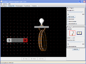
We know that
if there’s a magnetic field perpendicular to a current in a wire,
the wire moves perpendicular the field and the current.
But what happens if we move a wire in a magnetic field…? We get a
current induced in the wire
We can show this by moving wire connected to an ammeter through a magnetic
field. Move the wire in one direction we get a positive reading; and in the
other, a negative. But when there is no movement there is no current
We can use
this to identify that:
- Using a
magnetic field and movement we can create a current
- Using a
current and a magnetic field we create movement
- \ We can see that any combination of a
current, magnetic field and motion create the other one.
Model
question:
Explain
carefully how you can induce a current in a wire [3]
- The wire must
be perpendicular to the magnet
- The wire and
magnetic field must move relative to each other
- The wire must
cut through the magnetic field lines as it moves
- The induced
current perpendicular to both the field lines and the motion